Architects and Engineers Investigating Destruction of WTC Skyscrapers on September 11
Technical Analysis

NIST’s final report on the collapse of World Trade Center Building 7, issued in November 2008, has many flaws, including blatant fraud.
Part 1 of Chris Sarns’ report, which examines the burned-out fire in WTC 7, is available here.
Part 2 of Chris Sarns’ report, which examines NIST’s claim of thermal expansion, is available here.
Part 3 (below) was originally published on August 22, 2013.
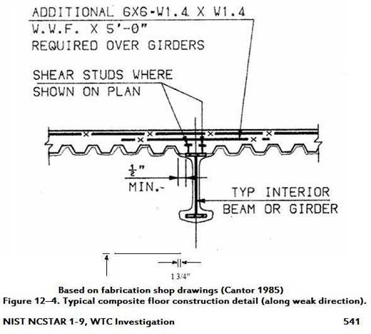
If we go back to its June 2004 Progress Report (and in the actual shop drawings*), NIST referenced shear studs, which are used to keep steel floor beams and girders in place and to impart stability and strength to buildings.
But in its final report four years later, NIST reworded its comments on shear studs to give the appearance that none were used on the floor girders.
Why would NIST make this fraudulent statement?
To know the answer, one needs to understand NIST’s collapse theory, which goes like this:
1. The key girder between column 79 and the exterior wall failed at Floor 13.
2. That failure caused the collapse of Floors 13 through 6.
3. Column 79, now unsupported laterally by these floors, buckled and brought down the entire building.
Obviously, this scenario posited by NIST sounds more credible if the key girder isn’t being held firmly in place with shear studs. So, then, by magically omitting the shear studs, NIST validates its theory that the key girder failed.
Compare the two quotes from NIST below.
In this first paragraph excerpt of its 2004 report, NIST says that studs were used with both beams and girders, although the studs “were not indicated on the design drawings for many of the core girders.” (By the way, the girder associated with column 79 was not a core girder.)
“Most of the beams and girders were made composite with the slabs through the use of shear studs.* Typically, the shear studs were 0.75 in. in diameter by 5 in. long, spaced 1 ft to 2 ft on center.** Studs were not indicated on the design drawings for many of the core girders.” — NIST June 2004 Progress Report, Appendix L, pages 6-7 [PDF pages 895-896]
In its August 2008 draft of the final report, however, not only does NIST drop mention of the association of girders with shear studs (in the first sentence of the excerpted paragraph below), but it then goes on to imply that studs were not indicated at all on the girders (in the last sentence of the same excerpted paragraph):
“Most of the beams [the words “and girders” are deleted] acted compositely with the slabs through the use of shear studs. Typically, the shear studs were 0.75 in. in diameter by 5 in. long, spaced roughly 1 to 2 ft on center. Studs were not indicated on the design drawings for [the words “many of the core” are deleted] the girders, i.e., composite action did not develop between the girders and the slab.” — NIST August 2008 Draft Report, NCSTAR 1-9, Vol. 1, page 15 [PDF page 59]
NOTE: NIST changed the wording of this section in the three months between its August 2008 draft report (see sentence directly above this note) and its November 2008 final report, which it newly worded this way: “Most of the beams acted compositely with the slabs through the use of shear studs. Typically, the shear studs were 0.75 in. in diameter by 5 in. long, spaced roughly 1 ft to 2 ft on center. The number of studs on a floor beam was indicated on the design drawings. Photographic records showing the demolition of a floor slab (tenant renovation) on the south side of a typical tenant floor confirms the number of studs shown on the drawings. Studs were not indicated on the design drawings for the girders, i.e., composite action did not develop between the girders and the slab.” — NIST November 2008 Final Report, NCSTAR 1-9, page 15 [PDF page 59]
Then, in this paragraph of the Final Report, NIST used the “absence” of shear studs to help make its case that:
“At Column 79, heating and expansion of the floor beams in the northeast corner caused the loss of connection between the column and the key girder. Additional factors that contributed to the failure of the critical north-south girder were (1) the absence of shear studs that would have provided lateral restraint and (2) the one-sided framing of the east floor beams that allowed the beams to push laterally on the girders, due to thermal expansion of the beams.” — November 2008 NCSTAR 1A, pages 53-54 [PDF pages 95-96]
This deliberate distortion of the evidence can only be called fraud. Even those who have accepted the official story must acknowledge that NIST’s misstatements of its own report are not mere mistakes. They are bending to accommodate a theory that cannot, under any circumstances, stand up.
*NCSTAR 1-9, Vol. 2, Figure 12-4 (below)
**The term “on center” means “apart.”
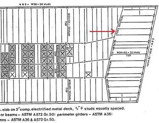
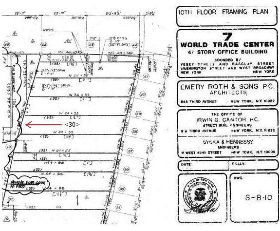
Structural engineer Ron Brookman found that the Salvarinas “Fabrication and Construction Aspects,” a document that outlines the basic structural system of WTC 7, shows 30 shear studs on the girder in question (see page 20 of the Seven World Trade Center link above the next graphic).
Seven World Trade Center, New York, Fabrication and Construction Aspects
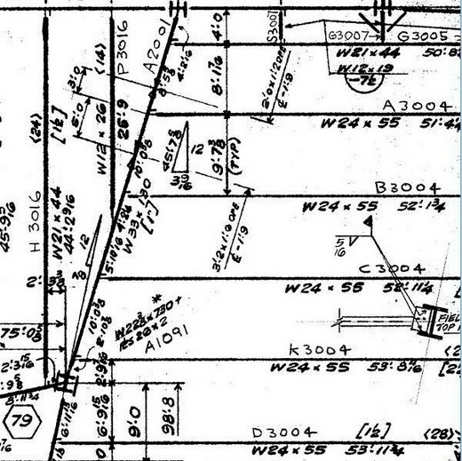
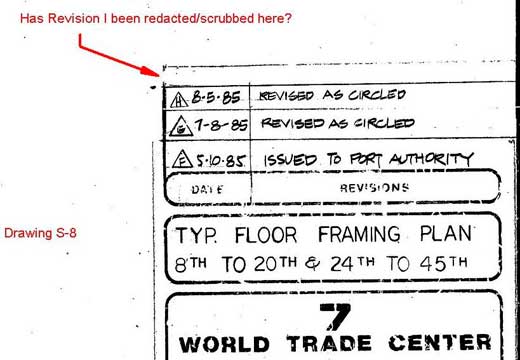
The erection drawings in the NIST final report show field-installed studs on the beams but not the girder between columns 44 and 79. A note on the drawing says, “For additional studs see cust. dwg. S8,” but the corresponding note has been erased.
See AE911Truth’s article titled WTC 7 Blueprints Exposed Via FOIA Request: Building Plans Allow for Deeper Analysis of Skyscraper’s Destruction
Drawing E12/13
NIST used a drawing without the shear stud notation in the final report on WTC 7. The space with the missing shear stud notation was instead used for the angle notation.
NIST did not release the “As built” drawings, which no doubt have the shear studs on the girder between columns 44 and 79.
A FOIA release in 2012 contained drawings that show <30> shear studs on that girder on Floor 10 and Floor 20. It is simply not consistent or logical to have shear studs on the girder on some floors but not on other floors. See drawings S-8-10 and S-8-20 below.


